Traffic Surveillance and Vehicle
Recording Solution Design Guide
A comprehensive guide for designing and implementing traffic surveillance and vehicle recording systems
System Overview
The Traffic Monitoring and Vehicle Recording System is a core infrastructure for modern intelligent transportation management. It provides real-time monitoring of road traffic conditions, vehicle information recording, violation evidence collection, and traffic flow analysis. This design guide offers a complete technical solution covering system planning, architecture design, product selection, installation and commissioning, and operations and maintenance.
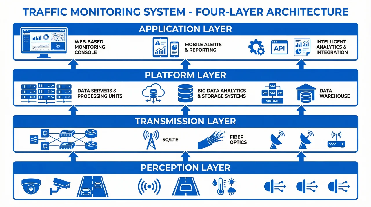
Figure 1: System Overall Architecture - Four-Layer Horizontal Architecture Model
Core Functional Modules
The system includes six core functional modules:
- Real-time Monitoring: Live video streaming and multi-screen display
- Vehicle Recognition: License plate recognition and vehicle type classification
- Violation Detection: Automated detection of traffic violations
- Data Storage: Video recording and structured data storage
- Intelligent Analysis: Traffic flow analysis and behavior recognition
- System Integration: Integration with traffic management platforms
Typical Application Scenarios
This system is widely deployed in the following scenarios:
- Urban Roads: Intersections, main roads, and expressways
- Highways: Toll gates, service areas, and tunnels
- Ports and Terminals: Container yards, freight channels, and entry/exit gates
- Campus Parking: Parking lots, campus roads, and access control
- Temporary Sites: Wireless applications, emergency deployments, and temporary monitoring
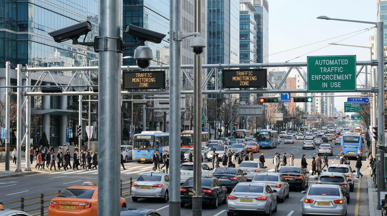
Figure 2: Urban Intersection Monitoring Scenario
Guide Contents
This design guide contains 12 main chapters covering the full lifecycle of system design, implementation, and operations:
- System Composition - System architecture and components
- Design Methodology - Design principles and methods
- Scenarios & Selection - Application scenarios and solution selection
- Architecture Design - System architecture design
- Selection & Interfaces - Product selection and interfaces
- Security & Risks - Security protection and risk management
- Supporting & Integration - Supporting systems and integration
- Tools & Materials - Tools and auxiliary materials
- Calculators - Practical calculators
- Quality & Acceptance - Quality standards and acceptance
- Installation & Debugging - Installation and commissioning
- Operations & Maintenance - Operations and maintenance support
Quick Navigation
Use the left sidebar navigation menu to quickly access each chapter. Each chapter contains detailed technical specifications, design points, implementation plans, and best practices.
Chapter 1: System Composition
System Architecture and Components
1.1 System Architecture
The Traffic Monitoring and Vehicle Recording System adopts a four-layer horizontal architecture design, from bottom to top: Perception Layer, Transmission Layer, Platform Layer, and Application Layer.
Figure 1.1: Four-Layer System Architecture
Perception Layer
The perception layer is responsible for collecting traffic information through front-end devices, including:
- High-definition cameras (supporting license plate recognition and face recognition)
- Supplementary lighting (infrared, white light, hybrid lighting)
- Protective housings and mounting brackets
- Sensors (loop detectors, radar, etc.)
Transmission Layer
The transmission layer is responsible for transmitting front-end data to the back-end platform:
- Wired transmission: Fiber optic, network cables, power cables
- Wireless transmission: 4G/5G, WiFi, microwave
- Transmission equipment: Switches, routers, optical modules
Platform Layer
The platform layer is responsible for data processing and business logic:
- Video management servers
- Storage systems
- Analysis servers
- Databases
Application Layer
The application layer provides various application services to users:
- Real-time monitoring applications
- Violation evidence collection applications
- Big data analysis applications
- Mobile applications
1.2 System Working Principle
The system workflow is as follows:
- Front-end cameras capture video and images
- Data is transmitted to the platform via the network
- Platform performs video decoding and analysis
- Extract license plates, faces, and other feature information
- Store original video and structured data
- Provide query and analysis functions
1.3 System Composition Key Points
| Layer | Main Equipment | Key Indicators | Notes |
|---|---|---|---|
| Perception Layer | Cameras, lighting | Resolution, frame rate, bitrate | Select based on scenario |
| Transmission Layer | Switches, fiber, cables | Bandwidth, latency, reliability | Redundant design |
| Platform Layer | Servers, storage, database | Processing capacity, storage capacity | High availability design |
| Application Layer | Software platform, clients | Functional completeness, usability | User experience |
Chapter 2: Design Methodology
Design Principles and Methods
2.1 Design Principles
- Reliability First: System design prioritizes high reliability
- Redundant Design: Critical links adopt redundant design
- Easy Maintenance: Design should facilitate daily maintenance and troubleshooting
- Cost-Effectiveness: Control costs while meeting requirements
- Scalability: System should support future expansion and upgrades
2.2 Design Key Points
During the design process, the following aspects need to be emphasized:
- Application scenario analysis
- Requirement specification definition
- Network topology planning
- Equipment selection
- Security protection
- Operations and maintenance support
2.3 Design Process
- Requirement Analysis - Clarify business requirements and technical indicators
- Solution Design - Develop system architecture and equipment configuration
- Detailed Design - Prepare construction drawings and technical specifications
- Procurement and Bidding - Equipment procurement and supplier selection
- Construction Implementation - Installation and commissioning according to drawings
- Acceptance and Delivery - Functional testing and quality acceptance
- Operations Support - Long-term maintenance and technical support
2.4 Design Best Practices
Best Practice Guidelines
- Conduct thorough site surveys before design
- Consider environmental factors (weather, lighting, obstacles)
- Plan for future capacity growth (20-30% reserve)
- Document all design decisions and rationale
- Involve stakeholders early in the design process
Chapter 3: Scenarios & Selection
Application Scenarios and Solution Selection
3.1 Typical Application Scenarios
Scenario 1: Urban Intersection
Urban Intersection Monitoring Scenario
Characteristics: High traffic volume, low vehicle speed, requires comprehensive monitoring.
Solution: 4-8 HD cameras, wired transmission, centralized storage.
Scenario 2: Highway Toll Gate
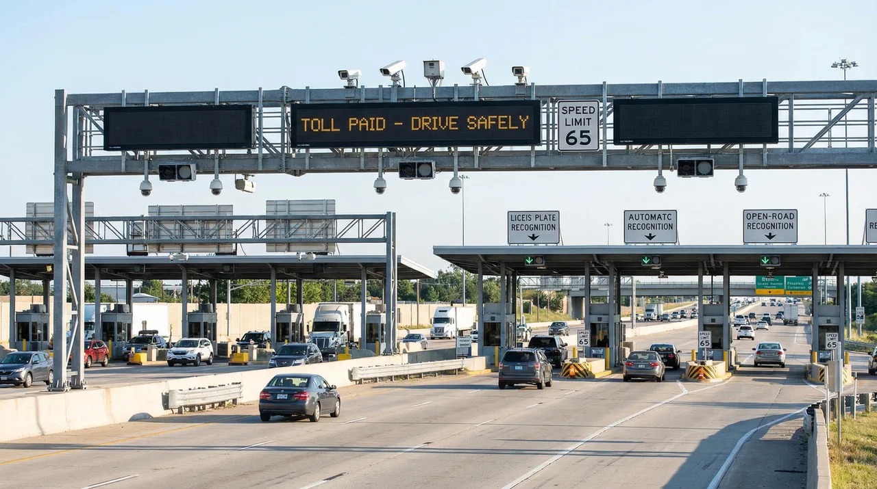
Highway Toll Gate Monitoring Scenario
Characteristics: High vehicle speed, requires precise recognition, 24/7 operation.
Solution: High-speed cameras, strong supplementary lighting, redundant transmission, local storage.
Scenario 3: Port and Terminal
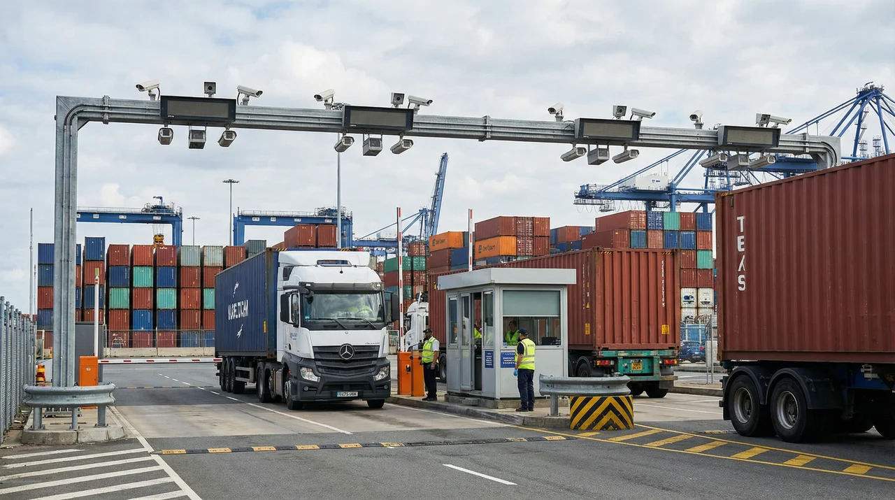
Port Container Gate Monitoring Scenario
Characteristics: Complex environment, poor lighting conditions, requires high-precision recognition.
Solution: Ultra-high-definition cameras, multi-spectrum lighting, professional analysis.
Scenario 4: Campus Parking
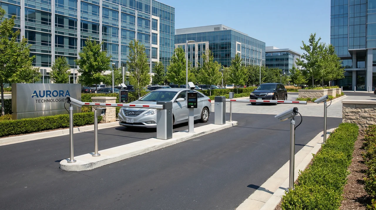
Smart Campus Parking Lot Monitoring Scenario
Characteristics: Moderate traffic flow, relatively stable environment, requires integration with barrier gates.
Solution: Standard HD cameras, wireless + wired hybrid, local processing.
Scenario 5: Temporary Monitoring Site
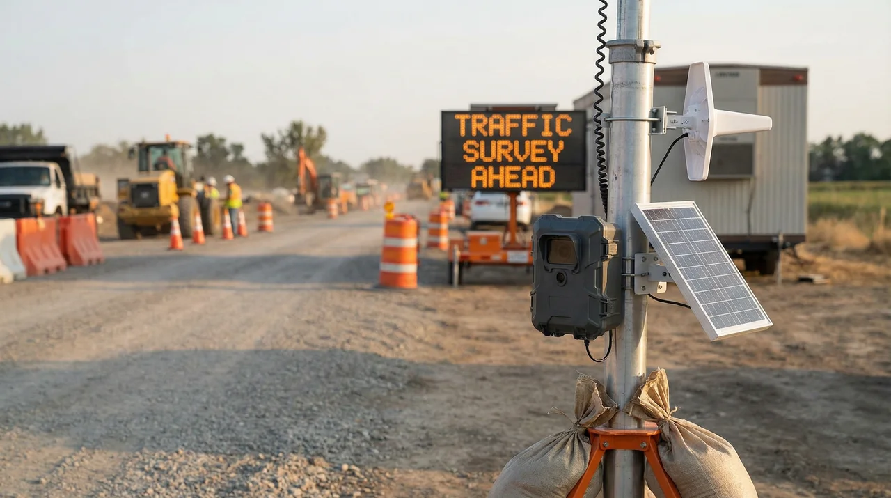
Temporary Traffic Monitoring Site
Characteristics: Requires rapid deployment, no fixed power supply, no network infrastructure.
Solution: Wireless cameras, solar power, 4G transmission, mobile storage.
3.2 Solution Comparison
| Scenario | Camera Count | Transmission Method | Storage Solution | Investment Scale |
|---|---|---|---|---|
| Urban Intersection | 4-8 channels | Wired fiber | Centralized storage | Medium |
| Highway Toll Gate | 6-12 channels | Wired + redundant | Local + centralized | High |
| Port Terminal | 10-20 channels | Fiber + wireless | Distributed storage | Very High |
| Campus Parking | 4-6 channels | Wired + wireless | Local storage | Low-Medium |
| Temporary Monitoring | 1-2 channels | 4G/WiFi | Mobile storage | Low |
Chapter 4: Architecture Design
System Architecture and Network Design
4.1 System Topology
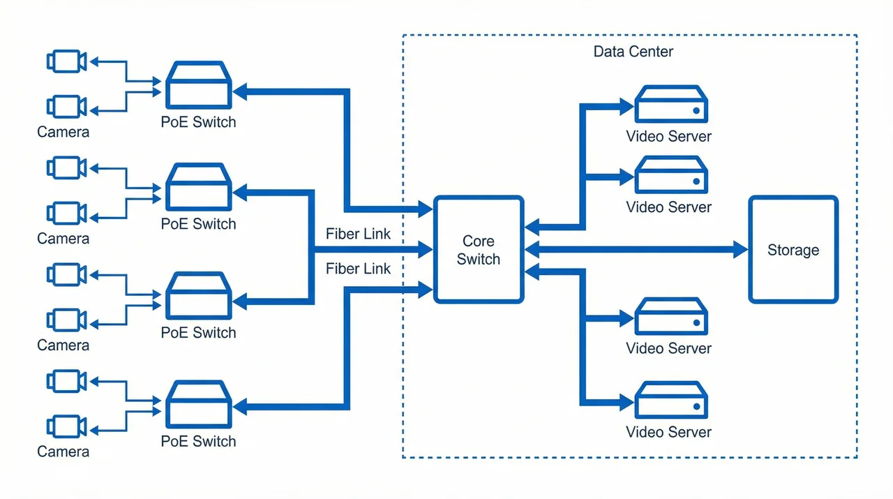
Figure 4.1: System Network Topology Diagram
4.2 Core Performance Indicators
| Indicator Category | Indicator Name | Target Value | Description |
|---|---|---|---|
| Availability | System Availability | ≥99.5% | Annual downtime ≤44 hours |
| Performance | Video Latency | <500ms | Real-time monitoring requirement |
| Performance | Recognition Accuracy | ≥95% | License plate recognition accuracy |
| Capacity | Storage Duration | ≥30 days | Adjustable based on requirements |
| Security | Data Encryption | AES-256 | Transmission and storage encryption |
4.3 Business Logic
The main business processes of the system include:
- Video Capture → Front-end cameras capture in real-time
- Video Transmission → Transmitted to platform via network
- Video Decoding → Platform performs H.264/H.265 decoding
- Intelligent Analysis → License plate recognition, face recognition, behavior analysis
- Data Storage → Original video and structured data storage
- Business Applications → Violation evidence, traffic analysis, big data mining
- User Query → Provide query, statistics, and export functions
4.4 Network Design Considerations
Key Design Points
- Bandwidth Planning: Calculate total bandwidth requirements based on camera count and bitrate
- Network Segmentation: Separate video network from management network using VLANs
- QoS Configuration: Prioritize video traffic to ensure real-time performance
- Redundancy: Implement link redundancy for critical connections
- Scalability: Reserve ports and bandwidth for future expansion
Chapter 5: Selection & Interfaces
Product Selection and Interface Specifications
5.1 Camera Selection
| Camera Type | Resolution | Frame Rate | Applicable Scenario | Price Range |
|---|---|---|---|---|
| Standard HD | 1080P | 30fps | General monitoring | Low |
| Ultra HD | 4MP/5MP | 30fps | License plate recognition | Medium |
| Full HD | 2MP | 30fps | Universal monitoring | Low-Medium |
| High Definition | 8MP/12MP | 30fps | High-precision recognition | High |
5.2 Wiring Specifications
Power Wiring
- Cameras: 12V DC or PoE power supply
- Supplementary lighting: AC 220V or 12V DC
- Equipment grounding: All equipment enclosures must be grounded
Video Wiring
- Network transmission: Cat6 network cable or fiber optic
- Analog transmission: BNC coaxial cable (only for analog cameras)
- Waterproofing: Outdoor connections must have drip loops
Control Wiring
- PTZ control: RS485 signal cable
- Alarm input: Dry contact or relay
- Alarm output: Relay normally open/normally closed contacts
5.3 Technical Specifications
Video Encoding
Supports H.264 and H.265 encoding. H.265 is recommended to reduce bandwidth consumption.
Network Protocols
Supports GB/T 28181 national standard protocol for easy integration with other systems.
Resolution and Bitrate
1080P@30fps recommended bitrate: 4-6Mbps; 4MP@30fps recommended bitrate: 6-8Mbps.
Chapter 6: Security & Risks
Security Protection and Risk Management
6.1 Security Architecture Design
Physical Security
- Equipment Anti-theft: Front-end equipment uses anti-tamper alarms, locked enclosures, and anti-climb pole designs
- Equipment Room Security: Access control systems, video surveillance, fire protection systems, environmental monitoring
- Cable Protection: Use metal conduits or cable trays to prevent intentional damage
Network Security
- Network Isolation: Physical or logical isolation between video network and office network using VLANs
- Access Control: Firewall policies, ACLs, 802.1X authentication
- Encrypted Transmission: HTTPS, TLS, wireless WPA2/WPA3 encryption
- Intrusion Detection: Deploy IDS/IPS for real-time monitoring of abnormal traffic
Data Security
- Data Encryption: Storage data encryption, transmission encryption
- Backup and Recovery: Regular backups, off-site backups, rapid recovery mechanisms
- Anti-tampering: Video watermarking, digital signatures, hash verification
- Permission Management: Principle of least privilege, role separation, operation auditing
6.2 Risk Assessment
| Risk Category | Specific Risk | Probability | Impact Level | Mitigation Measures |
|---|---|---|---|---|
| Technical Risk | Equipment failure | Medium | High | Redundant design, rapid spare parts |
| Technical Risk | Network attack | Low | Very High | Network isolation, intrusion detection |
| Environmental Risk | Lightning damage | Medium | High | Three-level lightning protection, grounding system |
| Management Risk | Untimely maintenance | Medium | Medium | Systematic inspections, alarm mechanisms |
6.3 Emergency Response Plans
Plan 1: Core Equipment Failure
Response Process: Automatic failover to backup equipment → Operations personnel respond within 15 minutes → Remote diagnosis → On-site spare parts replacement → Comprehensive testing
Recovery Objectives: RTO < 2 hours, RPO < 5 minutes
Plan 2: Network Attack
Response Process: IDS/IPS automatic blocking → Security administrator intervention → Isolate affected systems → Activate backup systems → Remove malicious code
Plan 3: Natural Disaster
Response Process: Activate emergency command → Assess damage → Prioritize restoration of core sites → Allocate resources → Phased recovery
Chapter 7: Supporting & Integration
Supporting Systems and Integration
7.1 Supporting Requirements
Power Supply System
- Mains power: AC 220V stable power supply, critical nodes require dual power supply
- UPS backup: Equipment room core equipment configured with UPS, backup time ≥30 minutes
- PoE power supply: Front-end cameras use PoE power supply to simplify wiring
- Solar power supply: Remote sites can use solar + battery solutions
Lightning Protection and Grounding System
- Level 1 lightning protection: Building lightning rods/strips to protect the main structure
- Level 2 lightning protection: Install surge protective devices (SPD) in distribution cabinets
- Level 3 lightning protection: Install signal surge protectors at equipment terminals
- Grounding system: Grounding resistance ≤4Ω (outdoor), ≤1Ω (equipment room)
Structured Cabling System
- Fiber optic: Main backbone uses single-mode fiber, reserve redundant fiber cores
- Network cable: Cat6 or higher, supports gigabit transmission
- Conduit: Use PVC or galvanized steel pipe for protection
- Labeling: All cables clearly labeled at both ends
7.2 Cross-System Interfaces and Integration
Integration with Traffic Police Comprehensive Platform
Interface Protocol: GB/T 28181 or vendor proprietary protocol
Data Exchange: Violation capture images, vehicle passage records, real-time video streams
Integration with Toll Collection System
Interface Protocol: TCP/IP Socket or Web Service
Data Exchange: License plate recognition results, vehicle images, transaction association
Integration with Parking Management System
Interface Protocol: HTTP/HTTPS RESTful API
Data Exchange: Vehicle entry/exit records, license plate recognition, billing information
Integration with GIS Map System
Interface Protocol: Standard map services (WMS/WMTS)
Data Exchange: Device locations, video preview, event annotations
7.3 Integration Architecture Design
Integration Mode Selection
Point-to-Point Integration: Suitable for scenarios with few systems and simple interfaces
ESB Bus Integration: Suitable for complex multi-system integration with unified data exchange
API Gateway Integration: Suitable for microservice architecture with unified interface management
Chapter 8: Tools & Materials
Tools and Auxiliary Materials
8.1 Essential Tools List
Electrical Tools
| Tool Name | Specification Requirements | Purpose | Recommended Quantity |
|---|---|---|---|
| Multimeter | Digital, 0-600V range | Measure voltage, current, resistance | 2 units |
| Ground Resistance Tester | 0-200Ω range | Measure ground resistance | 1 unit |
| Insulation Resistance Tester | 500V/1000V test voltage | Measure cable insulation | 1 unit |
| Soldering Iron | 60W adjustable temperature | Solder electronic components | 1 set |
| Wire Stripper | 0.5-6mm² | Strip cable insulation | 2 pieces |
| Crimping Tool | Compatible with RJ45/RJ11 | Make network cable connectors | 2 pieces |
Network Tools
| Tool Name | Specification Requirements | Purpose | Recommended Quantity |
|---|---|---|---|
| Cable Tester | Supports Cat5e/Cat6 testing | Test cable continuity and wiring | 2 units |
| Optical Power Meter | -50~+26dBm range | Measure fiber signal strength | 1 unit |
| Fiber Fusion Splicer | Single/multi-mode, loss <0.02dB | Splice fiber optic cables | 1 unit |
| Fiber Cleaver | 16-position | Cut fiber optic cables | 1 piece |
8.2 Product Images
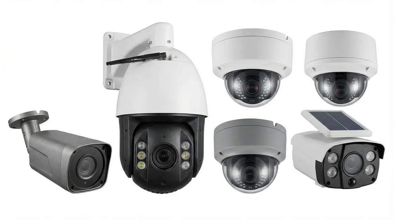
Figure 8.1: Various Traffic Monitoring Camera Products
8.3 Auxiliary Materials List
Cable Types
- Cat6 network cable: Outdoor waterproof type
- Single-mode fiber: 8-core/12-core
- Power cable: BVR 2.5mm²/4mm²
- Ground wire: BVR 6mm²
- RS485 signal cable: RVSP 2×0.75mm²
Connector Types
- RJ45 connectors: Cat6 shielded type
- Fiber connectors: LC/SC
- Waterproof connectors: M20/M25
- Terminal blocks: UK series
- Crimp terminals: Multiple specifications
Protection Materials
- PVC conduit: Φ20/Φ25/Φ32
- Galvanized steel pipe: Φ25/Φ32
- Cable tray: 100×50/200×100
- Waterproof tape: 3M
- Cable ties: Multiple specifications
- Labels: Waterproof type
8.4 Spare Parts Strategy
| Equipment Type | Spare Parts Ratio | Storage Location | Replacement Cycle |
|---|---|---|---|
| Cameras | 2-5% | Equipment room warehouse | Upon failure |
| Switches | 1-2 units | Equipment room warehouse | Upon failure |
| Hard drives | 10% | Equipment room warehouse | 3-5 years or SMART alert |
| Power adapters | 5% | Equipment room warehouse | Upon failure |
| Optical modules | 2-3 pieces | Equipment room warehouse | Upon failure |
| UPS batteries | 1 set | Equipment room warehouse | 3-5 years |
Chapter 9: Calculators
Practical Calculators
9.1 Storage Capacity Calculator
9.2 Network Bandwidth Calculator
9.3 PoE Power Calculator
9.4 Usage Instructions
Calculator Usage Tips
- Storage Capacity Calculator: Used to estimate the required hard disk capacity for video storage systems. Redundancy factor should be set to 1.2-1.5 to account for bitrate fluctuations and system overhead.
- Network Bandwidth Calculator: Used to plan network link bandwidth. Management traffic overhead includes protocol overhead, heartbeats, alarms, etc., typically 10-15%.
- PoE Power Calculator: Used to select PoE switches with appropriate power ratings. Power reserve is recommended at 20-30% to accommodate equipment startup transient power consumption and future expansion.
Note: The above calculation results are for reference only. Actual selection should also consider equipment specifications, environmental factors, etc.
Chapter 10: Quality & Acceptance
Quality Standards and Acceptance
10.1 Quality Differentiation
High-Quality Installation Characteristics
- Cables are neat and organized, with clear labels on each cable
- Equipment is securely mounted with no wobbling, screws properly tightened
- Terminal connections are firm with no looseness or exposed wires
- Waterproofing is standardized, seals are intact, drip loops are in place
- Ground wire connections are reliable, ground resistance meets standards
- Cabinet ventilation is good, equipment spacing is reasonable
- Labeling system is complete, facilitating maintenance
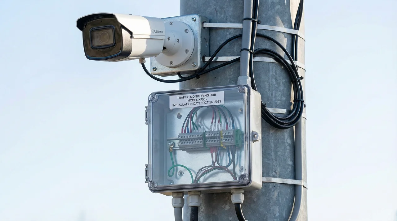
Figure 10.1: Example of High-Quality Professional Installation
Poor-Quality Installation Characteristics
- Cables are messy and tangled, with no labels
- Equipment installation is loose with obvious wobbling
- Terminal connections are loose with exposed wires
- Waterproofing is not standardized, seals are not tight
- Ground wire is loosely connected or not connected
- Equipment is too densely packed, poor ventilation
- No labels or labels are confusing
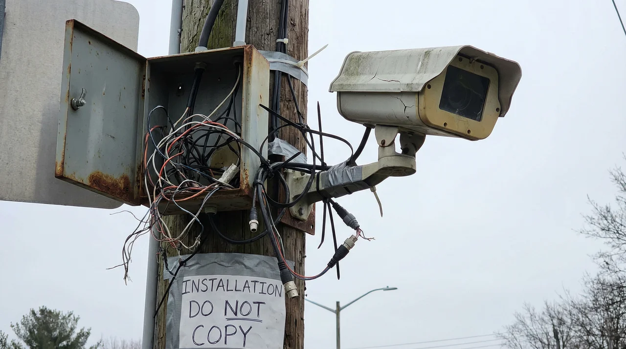
Figure 10.2: Example of Poor-Quality Installation (What to Avoid)
10.2 Acceptance Standards and Test Items
| Test Category | Test Item | Test Method | Acceptance Criteria |
|---|---|---|---|
| Functional Testing | Real-time video viewing | Client login, cycle through all channels | Images display normally, control latency <500ms |
| Recording and playback | Search and playback recordings at specified times | Recording files are complete, playback is smooth | |
| License plate recognition | Test with test vehicles | Recognition rate meets specified indicators | |
| Intelligent analysis | Trigger various events for testing | Detection is accurate, alarms are timely | |
| Performance Testing | Network bandwidth | Use traffic monitoring software | Bandwidth meets design values |
| Storage performance | Start recording on all channels simultaneously | Storage system has no IO bottlenecks | |
| Electrical Safety | Ground resistance | Measure with ground resistance tester | ≤4Ω (outdoor) |
| Reliability | Power recovery | Disconnect and reconnect equipment power | Equipment automatically restarts and resumes service |
10.3 Quality Comparison Summary
Key Quality Indicators
High-Quality Installation: Professional cable management, secure mounting, proper waterproofing, reliable grounding, complete labeling, and good ventilation. These characteristics ensure long-term system reliability and ease of maintenance.
Poor-Quality Installation: Messy cables, loose connections, inadequate waterproofing, poor grounding, and missing labels. These issues lead to frequent failures, difficult troubleshooting, and shortened equipment lifespan.
Chapter 11: Installation & Debugging
Installation and Commissioning
11.1 Pre-Installation Requirements
Environmental Preparation
- Road construction permits have been obtained
- Pole foundation curing is complete (concrete strength meets standards)
- Equipment room renovation is complete, environment meets standards
- Power supply system is in place, voltage is stable
- Network fiber is connected or wireless frequency planning is complete
Risk Pre-Check Checklist
- High-altitude work safety equipment inspection (safety belts, helmets, non-slip shoes)
- Temporary power line insulation inspection
- Underground pipeline exploration (avoid cutting)
- Traffic diversion measures in place
- Equipment unpacking inspection (appearance, model, accessories)
- Equipment specification and model verification
- Installation drawing confirmation
- Camera parameter pre-adjustment
- Software licensing ready
- Spare parts verification
- Weather forecast check
- Emergency contact confirmation
11.2 Construction Standards
Standard Key Points
- Neat Cable Routing: Cables laid neatly along walls and cable trays
- Separate Power and Signal: Distance ≥30cm, cross at right angles
- Clear Labeling: Cable labels at both ends, including start/end points and type
- Reliable Grounding: All equipment enclosures grounded, ground resistance meets standards
- Adequate Spacing: Reasonable equipment spacing for heat dissipation and maintenance
- Proper Protection: Outdoor equipment waterproof and dustproof, indoor equipment dustproof
Common Errors and Consequences
| Common Error | Consequence | Correct Practice |
|---|---|---|
| Unstable pole foundation | Pole tilting or collapse | Construct according to drawings, cure to standard before installation |
| Incorrect camera direction | Unable to capture effective images | Site survey, confirm monitoring direction |
| Screws not tightened | Equipment displacement or falling | Use torque wrench, tighten to specified torque |
| Lens protective film not removed | Blurry images | Remove protective film after installation |
| Cable entry without drip loop | Rainwater flows into equipment | Make U-shaped drip loop at cable entry |
| Equipment spacing too tight | Overheating and crashes | Maintain equipment spacing ≥1U |
11.3 Debugging Methods
Debugging Process
- Single Device Power-On: Check device indicator lights, confirm normal startup
- Network Configuration: Set IP address, gateway, subnet mask
- Platform Access: Add device in VMS, test connectivity
- Image Adjustment: Adjust angle, focus, exposure, lighting
- Function Testing: Test recording, playback, intelligent analysis
- Joint Debugging: Multi-system linkage testing
Problem-Solving Approach
Black Screen
Check: Power supply normal → Video cable connected → Network connected → Lens cap removed → Configuration correct
Blurry Image
Check: Adjust focus → Clean lens → Check resolution settings
Network Not Connected
Check: Network cable connected → Switch normal → IP address conflict → Firewall blocking
Low Recognition Rate
Check: Adjust angle → Adjust lighting → Adjust exposure → Adjust recognition area
Chapter 12: Operations & Maintenance
Operations and Maintenance Support
12.1 Operations and Maintenance Requirements
Maintenance Cycles
- Daily: Remote inspection, check device online status and alarms
- Weekly: Generate health reports, analyze system operation status
- Quarterly: On-site cleaning, check equipment appearance and environment
- Annually: Comprehensive inspection, including performance testing and security assessment
SLA and Response Levels
| Priority | Fault Description | Response Time | Recovery Time |
|---|---|---|---|
| P1 (Emergency) | Core business interruption, large-scale device offline | 15 minutes | 2 hours |
| P2 (Important) | Major function impaired, partial device failure | 30 minutes | 4 hours |
| P3 (General) | Single device failure, does not affect overall | 2 hours | Next business day |
| P4 (Inquiry) | Usage consultation, optimization suggestions | 8 hours | As scheduled |
12.2 Daily Monitoring
Monitoring Items
- Power Monitoring: UPS status, battery level, mains power status
- Temperature Monitoring: Equipment room temperature and humidity, equipment temperature
- Link Monitoring: Network connectivity, bandwidth utilization, packet loss rate
- Device Monitoring: Online status, CPU/memory usage, disk health
- Business Monitoring: Recording completeness, recognition accuracy, alarm count
12.3 Common Hazards and Prevention
| Hazard | Consequence | Prevention Measures |
|---|---|---|
| Spider webs blocking lens | Blurry images, recognition failure | Regular cleaning, use insect repellent |
| Leaves blocking view | Obstructed view | Regular tree trimming |
| Ground corrosion | Lightning protection failure | Anti-rust treatment, regular inspection |
| Fan dust accumulation | Poor heat dissipation, equipment overheating | Regular cleaning of fans and filters |
| Hard drive lifespan expired | Data loss, recording interruption | Monitor SMART, replace proactively |
| Configuration accidentally changed | Function abnormal | Regular configuration backup, permission control |
| Password not changed for long time | Security risk | Mandatory periodic password change |
| Log disk full | System abnormal | Set log rotation policy |
12.4 Troubleshooting and Repair
General Process
- Discover Phenomenon: Detect anomalies through monitoring or user feedback
- Collect Information: Check logs, alarms, monitoring data
- Initial Localization: Determine fault layer (front-end/transmission/platform)
- Isolate Fault: Determine fault scope, prevent spread
- Implement Repair: Replace equipment, modify configuration, restart services
- Verify Recovery: Test functions, confirm normal recovery
- Record Review: Record fault cause and handling process, summarize experience
Typical Fault Cases
Case 1: Single Camera Image Stuttering
Cause: Network cable connector poor contact
Handling: Remake connector, test network connectivity
Case 2: All Camera Timestamps Jumping
Cause: NTP server abnormal
Handling: Check NTP server, re-synchronize time
Case 3: Nighttime Recognition Rate Plummets
Cause: Supplementary lighting failure
Handling: Replace supplementary lighting
Case 4: Platform Query Recording Slow
Cause: Database index fragmentation
Handling: Optimize database, rebuild indexes
Case 5: PTZ Cannot Be Controlled
Cause: RS485 control line open circuit
Handling: Measure line, repair break point
Case 6: Frequent Disk Failure Alarms
Cause: RAID card battery aging
Handling: Replace RAID card battery
12.5 Operations and Maintenance Best Practices
Success Factors for Operations and Maintenance
- Prevention First: Proactively discover and resolve issues through monitoring and inspections
- Rapid Response: Establish comprehensive alarm mechanisms and emergency plans
- Continuous Improvement: Regularly summarize experience and optimize operations processes
- Knowledge Accumulation: Build fault case libraries and knowledge bases
- Team Collaboration: Clear division of labor and enhanced communication
- Skill Enhancement: Regular training to maintain technical updates